Unfortunately I decided to write this some time after I did it, so half is from my memory. Hopefully about correct!
After 10 years of service my Squeezebox Boom display went dead. Seems I’m not alone, Joe’s tech blog has very good story about this including a fix, see here.
Disassembled mine and was about to install the diode hack, but then decided to look a bit deeper. Didn’t find schematics anywhere so started following PCB traces. Filament power feed is clear, there’s two related transistors visible and easy to check. Mine were fine. The diode hack side is tricky, the components are under the VFD, which is hard to remove without breaking it or the PCB unless you have skills and the right tools. Be warned. I have tools and managed to remove it without issues.
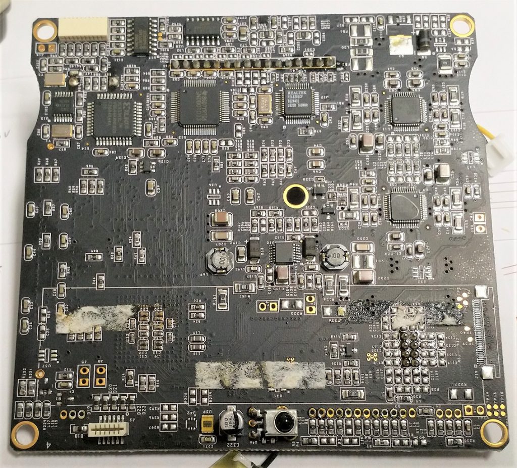
The VFD is soldered, but has also (very) sticky tape under it, remove it veeery carefully if you decide to do this. On the image above left bottom corner you can see two SMD transistors (Q7 and Q1). Those tiny ones seem to drive the display. A PNP drives the display filament (to ground) and is controlled by an NPN transistor.
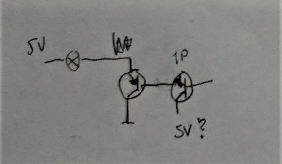
On my board the driving transistor had obviously been hot, since the PCB was slightly burned looking through a microscope (one trace also broke when removing it). Just to be sure I replaced the other transistor also. These are marked with SMD codes sometimes hard to translate, ‘W1P’ and ‘N5Xe’. W1P is likely PMBT2222A, common NPN switching transistor. Had a ‘1P’ and used that. The other one was more tricky as I didn’t find that code. Unless it’s a fet it must be PNP (experimented with 2N4403 and a 10 ohm resistor on behalf of the filament and yes, now there was current!). The TO92 case transistor went hot super quick as must have the original tiny SMD done as well, looks quite under-dimensioned to me. So I wanted to put something better there. Looking at the mechanics it struct me that there is actually space for a TO126 case, and it can also be fastened easily with the existing screw:
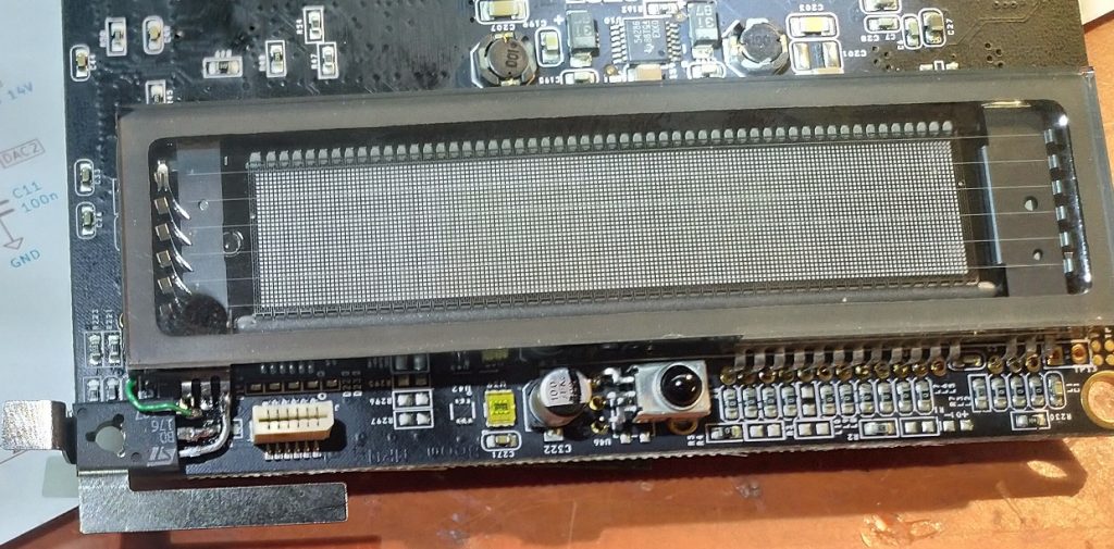
Before soldering the display back, solder a wire to the base of the removed SMD transistor (the pad directly connected to the other transistor). From junk box I found BD176, a 3A PNP power transistor. Pins are E-C-B, so cut most of the base and solder the wire to that pin. Then cut the collector / middle pin and solder it to ground (D18 perfectly located). Bend emitter 90 degrees and solder it to the display, see image above.
And what do you know, it works again! The only issue seen so far is the dimming level is not exactly as it was. The lowest level is almost invisible. This is perhaps caused by not using transistors with the same exact characteristics or maybe the display is also getting old. Close enough for me. Has now worked fine for a month or so, boom on!