Cheap regulators from China

I buy a lot of components from Chinese ebay sellers. I do know quite well those are not always what they are supposed to be even when listed “new, original”. Most of the time I’ve been satisfied with what I got. Usually I use these for keeping a stash for experiments that would not happen with normal component pricing. I often buy more reliable components for power supplies and such that could generate further damage. Anyhow this case triggered me to write a story to keep in mind.

So I needed one vintage chip (did work as expected). Found a seller and noticed they also listed cheap 78xx and 79xx regulators. I like to keep those available for sudden inspiration so I ordered a few. Listing was very cheap, like a few dollars for 20 pcs of 78xxCV TO220 (unfortunately I forgot the seller as I used these two years later). Got those and gave positive feedback as they looked ok and didn’t need any just then.

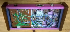
Time passed and recently I built a power supply for my eurorack synth. Used those linear regulators (7912 + 7812 + 7805). Yeah, don’t know why I used those for a power supply for potentially expensive gear. Built it, measured the voltages and all looked fine. Great. Then just happened to think maybe I’ll measure the current limit and look at the ripple before testing any modules. The transformer is a 40VA 2x12V one (rated 1.25A per coil), so I’d expect at least 1A per rail (+/- 12V). Hookup variable load, testing 12V rail first. Increasing load shows the voltage stays nicely at 12V and looks good, but when passing about 300mA load it drops to 0. What? Same story with -12V and +5V. Whaaat?

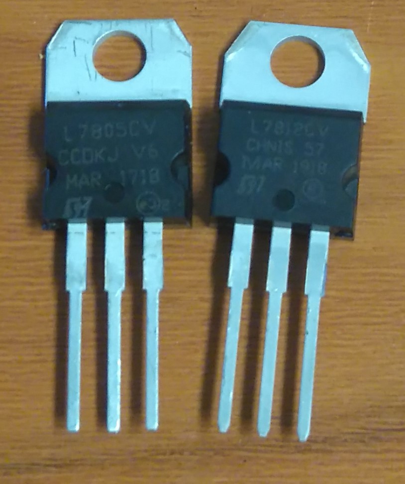
Nothing wrong with transformer or rectifier. When output drops to 0 the input side was still over 15V, more than enough to maintain the output (dropout spec is 2V for L7812CV). Whats’s the problem? Problem is all these 3 regulators are likely not actual 78/79xxCV as listed, but something else. Good news is there is overload protection unlike one switched mode regulator I got earlier from another seller (through it was a fantastic show with smoke effects and small explosion in the end!). Bad news is it’s way below datasheet listed at 1.5A (-> ~300mA). Changed all 3 to genuine ones from local shop and now get easily 1A. So my cheap regulators do work somehow, but are way below spec. Not fully unexpected for very cheap stuff from China, be aware. Most of the time however I do get usable components if not perfectly to specs.

Not exactly what printing says. Text is also tilted a bit

I still order cheap components from China for various projects, but once again it’s a good reminder you often get what you pay for.

Squeezebox Boom display fixed!

Unfortunately I decided to write this some time after I did it, so half is from my memory. Hopefully about correct!

After 10 years of service my Squeezebox Boom display went dead. Seems I’m not alone, Joe’s tech blog has very good story about this including a fix, see here.

Disassembled mine and was about to install the diode hack, but then decided to look a bit deeper. Didn’t find schematics anywhere so started following PCB traces. Filament power feed is clear, there’s two related transistors visible and easy to check. Mine were fine. The diode hack side is tricky, the components are under the VFD, which is hard to remove without breaking it or the PCB unless you have skills and the right tools. Be warned. I have tools and managed to remove it without issues.

The VFD is soldered, but has also (very) sticky tape under it, remove it veeery carefully if you decide to do this. On the image above left bottom corner you can see two SMD transistors (Q7 and Q1). Those tiny ones seem to drive the display. A PNP drives the display filament (to ground) and is controlled by an NPN transistor.

Something like this…

On my board the driving transistor had obviously been hot, since the PCB was slightly burned looking through a microscope (one trace also broke when removing it). Just to be sure I replaced the other transistor also. These are marked with SMD codes sometimes hard to translate, ‘W1P’ and ‘N5Xe’. W1P is likely PMBT2222A, common NPN switching transistor. Had a ‘1P’ and used that. The other one was more tricky as I didn’t find that code. Unless it’s a fet it must be PNP (experimented with 2N4403 and a 10 ohm resistor on behalf of the filament and yes, now there was current!). The TO92 case transistor went hot super quick as must have the original tiny SMD done as well, looks quite under-dimensioned to me. So I wanted to put something better there. Looking at the mechanics it struct me that there is actually space for a TO126 case, and it can also be fastened easily with the existing screw:

Perfect fit? The metal piece also serves as small heat sink (does not get really hot any more)

Before soldering the display back, solder a wire to the base of the removed SMD transistor (the pad directly connected to the other transistor). From junk box I found BD176, a 3A PNP power transistor. Pins are E-C-B, so cut most of the base and solder the wire to that pin. Then cut the collector / middle pin and solder it to ground (D18 perfectly located). Bend emitter 90 degrees and solder it to the display, see image above.

And what do you know, it works again! The only issue seen so far is the dimming level is not exactly as it was. The lowest level is almost invisible. This is perhaps caused by not using transistors with the same exact characteristics or maybe the display is also getting old. Close enough for me. Has now worked fine for a month or so, boom on!

MiniSynth – a summer project

I found an article about Arduino-based simple synthesizer at http://blog.dspsynth.eu/build-the-minimo-synth and thought that’s a great idea for a quick summer project. Googling a bit more I discovered the Mozzi-library, but for some reason I had trouble making it do what I wanted. Then I discovered similar code for a synth engine ( https://github.com/dzlonline/the_synth), that looked like doing most of what I wanted, so I took the engine and added some new functions like low-pass filter and possibility to dump and load the settings. The filter I implemented takes too long compute time to enable per-voice, so it is a common filter applied to the mix of all 4 voices provided by the original engine. Maybe could be optimized someday. And also add note off – the original engine does not have an  easy way to stop a sound.

It runs on 16MHz Arduino pro mini (or any other ATmega328). For the user interface I added 6 pots for parameters, a button to select voice and special functions, 2 LEDs and a 4-digit 7-segment LED display module (TDI-1400) I found from junk bin. MIDI interface is using PC900 opto isolator. Schematics can be found at github with the code (not fully finished, but works). BE WARNED, that I did not built it using those schematics which were drawn later trying to remember what I changed. Should be fine however. It uses both Arduino pins 9 and 11 for the sound, so can also work with the defaults for Mozzi.

My build is a bunch of wires and hot glue, but it seems to work. The case is made from junk aluminum profile with the mandatory vintage wooden ends fastened with 3D-printed brackets. 5-pin DIN for MIDI input, DC plug for power and audio jack for the line output. Front panel is a printed paper glued to the box and then sprayed with matt lacquer (is that English or Finglish?).

User interface is simple. You use the button to select which of the 4 voices you want to change and then just turn the pots (waveform, octave, envelope, length, pitch mod, mod speed). 5th button press activates “shift” and makes it possible to change common settings like filter cutoff and resonance, MIDI channel base (uses 4 consecutive channels in multi-timbral mode), save or load settings and select multi- or monotimbral mode. In monotimbral mode it uses the same setup for all oscillators and can play chords up to 4 notes (first note priority). Filter modulation is not yet implemented in SW.

Here’s a piece of a quick test song:

Only slight reverb and delay is added. Things to improve, but sounds quite good given the simple implementation. All parts were from junk boxes so did not really cost anything.

Evolution? – perhaps use a faster 32-bit CPU and 16-bit HW DAC for much more advanced synth. 8-bit AVR seems to be able to do actually more than I thought, but does have limitations for real-time audio processing. I do have unused ESP32, Teensy3 and nRF52 boards somewhere…

Welcome

Never really got the time to update the old HobbyLabs – site. This is an attempt to make it easier and perhaps find the time to actually put something new here. I’ll be gradually moving the old stuff here.

Most of the hobby time I use on vintage computing projects, DIY home automation and musical instruments. Might also make some measurement devices like an ongoing 20A DC load project. I can mostly manage with digital electronics, analog technology is sometimes a struggle not to mention RF.

So those are the potential topics I’ll mostly be sharing. Come back later, perhaps you can find something useful here. Do note, that these are hobby projects and some just quick experiments, so nothing is guaranteed to actually work!

I’ll enable commenting once things are a bit more stabilized.